As I wrote in my previous blog, I want to finalize my thoughts and move on the other subjects that are equal in importance and safety!
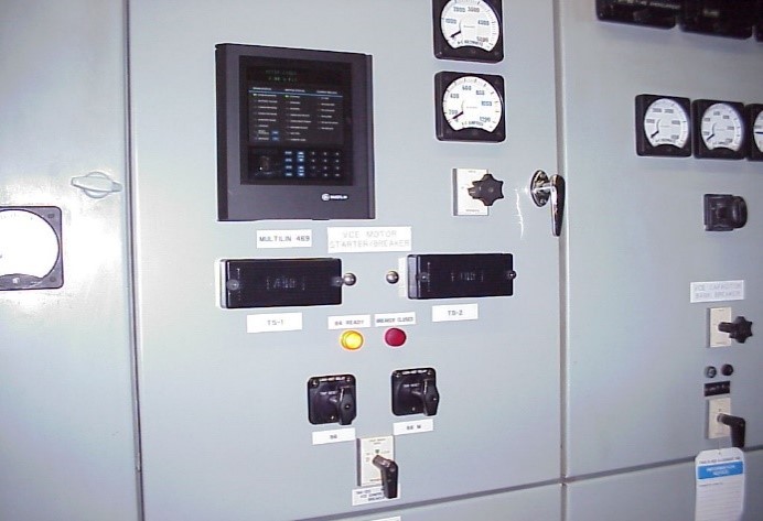
A decision must be made and mine would be to have a smart meter installed (if not already) and use that meter to determine Zero/energy. The non-contact detector can be used as an additional way of ensuring the power is off, indicating lights, and other items that change state when energized/de-energized can also be observed.
Have all the information I would need for Cal/Cm2, fault currents, cable sizing and type of clamps needed for positive connection to the bus bars. At one plant, we installed grounding ball clamps (trailer hitch style) on the bus and had cables made to fit the grounding ball connector. It was a very good/safe way of grounding the bus after we performed the required Zero energy check.
This is a grounding breaker in which I will explain on my next blog, but for now just bringing other thoughts and procedures that could be implemented.
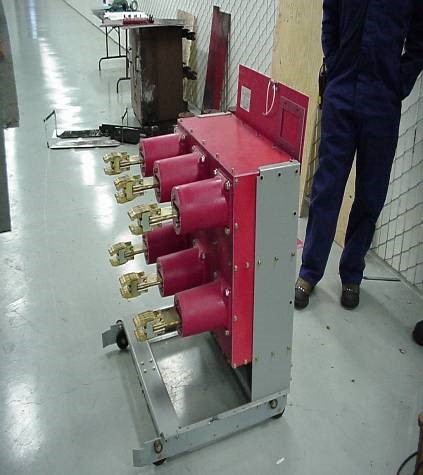
The grounding of switchgear bus and equipment must be taken very seriously and is extremely dangerous no matter what!
The main problem I have seen in the field with manufactured grounding devices such as the grounding breaker above is that the materials, the sizing of bus connections and cables, the method of racking in and out, the shielding used and more, are for the most part NOT ADQUATE for the purpose served. So the follow information is provided for your consideration.
January 31, 1994, OSHA issued the document 29CFR 1910.269 Subpart R. This document covers all aspects of work on or near energized power lines and equipment. The Institute of Electrical and Electronic Engineers (IEEE) has undertaken the preparation of several new documents dealing with the application of grounds and to provide recommended procedures for their use.
In addition, and with the newly added attention, ASTM (American Society of Testing and Materials) is currently revising the ASTM F855-96 standard, which specifies the minimum performance of the equipment that is used in grounding. At utilities, work practices and requirements are being reviewed to ensure conformance with the actions of OSHA, IEEE, and ASTM.
Purpose of the Ground Clamp and How it works
Ground Clamps form the interface or connection between the parallel installed low resistance grounding cable and the conductor being serviced. They are an integral part of the worker’s safety equipment. Good, adequate grounds can be the difference between life and death! Literally!
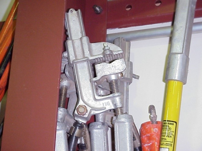 Clamps for protective grounds come in several styles and sizes for a variety of uses. Originally, the form was a basic C-Type clamp, which usually required a bucket truck and two hands to apply. Later, a spring-loaded (Duckbill type) clamps were developed to increase the ease of application and positioning of the clamps on the conductors or bus. Special clamps were developed for certain applications such as large tubular bus, towers, Flat face type, etc. Grounding assemblies are now available for the specific applications; Tower leg grounds, Substation grounds, underground, ball and socket types used on switch pads and or service trucks. Clamps can be fitted with threaded eyescrews for installation by hot-line equipment or T-handles for application to towers.
Typically, a Lineman attempts to form a near equal-potential zone in which to work by connecting one clamp to the conductor and the other to a conducting pole band below his feet. Sufficient grounds are installed to carry the expected fault current.
Clamps and associated hardware are divided into grades based upon maximum fault-current duty. For example, a grade 5 clamp with 4/0 AWG cable must withstand 43kA for 15 cycles without loosening its conductive properties. Wire size 2/0 AWG is good for 20kA (see Table 1-1and 1-2). From this you can see that it is very important that you know the expected fault current at the grounding point. Clamps with ferrules are highly recommended for protective grounds. Cable directly placed under pressure terminals are good when new, however as time builds, so does corrosion and resistance. High heat from the fault current is sufficient to burn the cable, thereby eliminating worker protection.
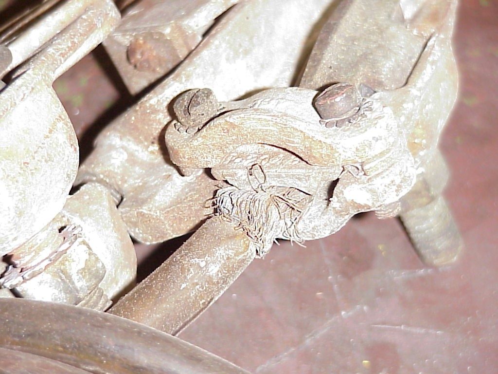 Loose ferrules and corrosion in the contact points can result in high resistance of the grounding set. When dealing with several thousands of amperes, a few milliohms resistance may make the difference between protection and injury or Death! For example, if it is desired to maintain a maximum of 100 Volts across a worker whose body resistance is 1,000 ohms during a fault of 10,000 amps, a parallel protective path of 10 milliohms or less is required. Any loose connection in the grounding cable assembly may increase the ground resistance, thus causing a higher potential to be placed across the worker. If the grounding system is 50 milliohms and the fault current is 10,000 amps, 500 Volts Vs 100 Volts is present.
Frequent inspections and low resistance measurements are strongly advised. Purchasing clear insulation ground cables, as 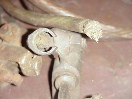 a set will help maintain the integrity of the grounding cable assembly, but cannot take the place of inspections prior to use. The actual grounding point can also introduce high resistance. Be sure to clean the surface to be used as the ground point, prior to application, especially in outdoor substations. Be sure to use only approved grounding clamps, rated for the expected fault current.
Safe Methods
Only two methods exist to maintain a safe current level in the normal working situation. One is to prevent the passage of current through the body by insulation means, or isolation from energized parts. Two provide a parallel path around the worker with such low resistance that all (hopefully) of the current takes the least path of resistance. A frequently used figure for human resistance is 1000 ohms, which would require a parallel path of resistance in the milliohm range. Several publications are available for the selection of and the usage of PPE gear (Personal Protective Equipment). Consult ASTM, IEEE, and NFPA 70E, to name a few.
No universal accepted or mandated regulation or document is available that will define the maximum allowable body current. One figure that is commonly used is for detecting current through the body is 1.2 milliamperes. The threshold of pain is approximately 9 milliamperes and the let-go threshold point is 16 milliamperes.
Before grounding, the circuit or equipment, it must be checked for zero energy by approved methods to be sure that the line or energized part is “Truly Dead”. Install the grounding cable ground lead to an appropriate ground bus or grid using an approved hot stick or at least rubber gloves rated for the circuit voltage. Then install the phase grounding leads starting with the closest phase conductor. “Do not tease the Bus”. When applying the grounding cables to the phase conductors, most experts in the Field agree that a deliberate, firm application of the ground clamp is the best. This will allow for upstream protective devices such as protective relays, fuses, and circuit breakers to see the fault and clear the circuit. Teasing the bus can, (if for some reason the circuit is re-energized during the time of the zero energy check and the application of the ground), cause severe arcing and blast conditions, exposing you directly.
Remember the Safety Slogan “If it is not Grounded, It’s not Dead”. This is an excellent truth that should be practiced at all times, however, improper grounding and in appropriate grounding equipment can introduce additional hazards that the electrician is not aware of.
The codes and standards used during the inspection included the following:
ANSI-C2 National Electrical Safety Code 1990
NFPA-70 National Electrical Code (NEC) 1990
IEEE-80 Guide for Safety in AC Substation Grounding
Guide for Measuring Earth Resistively, Ground Impedance, and Earth Surface Potentials of a Ground System Electric Power Distribution for Industrial Plants Grounding of Industrial and Commercial Power Systems Resources Code of Federal Regulations United States Department of the Interior.
Cable Test Methods:
To ensure the protective grounding equipment is always in a condition that offers maximum protection, periodic testing is implied. A variety of test methods have been developed. Among them are the AC millivolt drop, thermal warming at a current below the continuous level and low current Microhm measurements. An AC current source has always been the most readily available. For example, using a current transformer to step current up to the test level. However, the AC source has several problems associated with it. The cable must be uncoiled and physically placed on a nonconductive surface, in a parallel manner, to minimize the inductive effect. This is not always convenient when testing long cables or those stored on reels on line trucks. Thermal methods range from the subjective, feeling for heat with the hand, to the use of infrared temperature sensor devices and require a current of several hundred amperes in most cases.
The use of DC test current avoids all of these problems. Equipment can be tested when coiled and inductance is not a factor. Chance originally developed a manually operated, portable test device employing a variable 100 Amp DC source. Both current and resistance were metered and probes allowed testing either the entire set or individual connections within a set, to locate corroded (high resistance) connections.
An updated, programmable version of this DC tester was recently introduced. It is microprocessor controlled, eliminating the requirement for manual setting of the variable power supply. This feature alone represents a significant reduction in testing time. The elimination of the manually adjusted variable power supply provides a much lighter and more portable unit. The 100 Amp DC current source and the probe feature to locate individual corroded connections remain. Cable sizes being tested and the utility’s maximum voltage allowed across the worker are easily programmed from front panel switches. The digital readout shows an accurate measured resistance and is accompanied by pass/fail lights to help the operator identify a hazardous condition. The lights compare the utility’s maximum allowed worker voltage to the tested resistance at the ASTM F855-96 grounding equipment standard’s withstand current for the programmed cable size. The tester is now housed in a molded impact resistant case with the electronic circuitry fully contained on a state-of-the-art printed circuit board. In summary, the new unit is easier to use, more accurate, more portable and less fragile. It is expected to meet the assumed requirements of OSHA described above.
Jumpers and Grounds from AB Chance
Factory-assembly now gives another advantage to your Chance hot-line jumper and temporary-grounding sets. It’s above and beyond the high-grade fit and finish you already expect of the cable sets we custom build.
It’s in addition to our top-quality components, manufactured to applicable industry ratings (ASTM, ICEA, IEEE, and NEMA). It’s besides our in-plant techniques for trade-crafting ferrule-to-cable crimps. It’s even on top of our skills at applying clear stress-relief tubing at the connections so strands may be visually inspected in the field. And it’s past our precise torqueing of threaded fasteners for securing cable.
Testing of temporary grounds and jumpers cannot be overemphasized. Whether you specify the cable, clamps and connectors for us to build your sets or you select from our cataloged pre-assembled sets, we 100-percent test them upon completion.
Once in use, you periodically should test them. Likewise, you would test to initially check any sets you may build “from scratch” with components out of our open stock. But regardless of origin, testing on a regular basis should be an established procedure to verify low resistance of all protective-ground and hot-line jumper sets.
TABLE 1-1
Maximum Fault Currents of Grounding Cables
| Copper Cable Size AWG | Fault Time Cycles | RMS Amperes |
| 6 | 16,750 | |
| 2 | 15 | 12,000 |
| 30 | 8,550 | |
| 60 | 5,250 | |
| 6 | 25,250 | |
| 1/0 | 15 | 18,450 |
| 30 | 12,975 | |
| 60 | 8,000 | |
| 6 | 30,950 | |
| 2/0 | 15 | 20,850 |
| 30 | 14,950 | |
| 60 | 10,000 | |
| 6 | 40,580 | |
| 3/0 | 15 | 28,950 |
| 30 | 20,950 | |
| 60 | 13,000 | |
| 6 | 46,950 | |
| 4/0 | 15 | 36,950 |
| 30 | 25,950 | |
| 60 | 14,950 |
TABLE 1-2
Grounding Cable Quality Control Test Data
| Cable Size | # 2 | # 1/0 | # 2/0 | # 4/0 |
| Test Current | 200 Amps | 250 Amps | 300 Amps | 400 Amps |
| Cable Length | Voltage Drop Allowable | |||
| 4 FT. | 0.33 | 0.31 | 0.31 | 0.30 |
| 6 Ft. | 0.40 | 0.36 | 0.36 | 0.35 |
| 8 Ft. | 0.46 | 0.42 | 0.41 | 0.40 |
| 10 Ft. | 0.53 | 0.47 | 0.47 | 0.45 |
| 12 Ft. | 0.56 | 0.52 | 0.52 | 0.51 |
| 14 Ft. | 0.56 | 0.58 | 0.57 | 0.56 |
| 16 Ft. | 0.72 | 0.63 | 0.63 | 0.61 |
| 18 Ft. | 0.79 | 0.69 | 0.68 | 0.66 |
| 20 Ft. | 0.86 | 0.74 | 0.73 | 0.71 |
| 22 Ft. | 0.92 | 0.79 | 0.79 | 0.67 |
| 24 Ft. | 0.99 | 0.85 | 0.84 | 0.81 |
| 26 Ft. | 1.05 | 0.90 | 0.89 | 0.87 |
| 28 Ft. | 1.12 | 0.96 | 0.95 | 0.92 |
| 30 Ft. | 1.18 | 1.10 | 1.00 | 0.97 |
| 36 Ft. | 1.35 | 1.14 | 1.13 | 1.10 |
| 40 Ft. | 1.51 | 1.28 | 1.27 | 1.22 |
| 46 Ft. | 1.65 | 1.42 | 1.4 | 1.36 |
| 50 Ft. | 1.84 | 1.55 | 1.53 | 1.48 |
With all the information on the last 3 blogs, one must realize that this is not easy task, so use the information and do the job safely!